Poor performance may be caused by the following situations:
- The pump is suffering from gas interference due to the following:
- The high fluid level is compressing gas bubbles which is allowing these smaller sized gas bubbles to be carried downward with the oil or water into the pump intake
- The down-hole gas separator design is too small for your production rate
- The tubing anchor is restricting liquid flow back down through the anchor and gas is building up under the anchor allowing gas into the pump intake
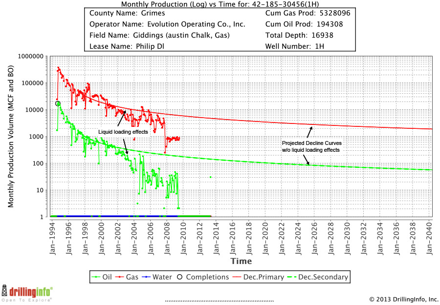
- The reservoir is flowing large gas slugs which is evacuating liquids around the pump while pushing liquids up the backside – common in horizontal laterals
- The tubing is restricted by a blockage from paraffin, scale, solids, collapsed tubulars…
- There is trash in the pump
- You have worn pump parts
Run a dynamometer analysis to determine if you can pinpoint the problem. GARP® can help with all the above problems except worm pump parts. GARP® can also provide methods for more efficient treating of paraffin, corrosion, and scale. Call a GARP® representative with your data so that a detailed analysis may be performed.
Basically a well is a GARP candidate as follows:
- Any well that has the existing artificial lift equipment installed a significant distance above the reservoir. Note: highly permeable reservoirs have lower distance requirements than less permeable reservoirs.
- Wells with reservoirs that are depletion drive or partial depletion drive and do not currently have artificial lift installed
- Wells that have 4-1/2” casing sizes or larger
- Wells with liners larger than 4” (it may be possible for 3-1/2” liners). Contact us
- Wells with severe paraffin problems
- Wells that need a more effective chemical treatment system
- Wells with remaining reserves that justify the installation costs (Higher EUR wells generally have more remaining reserves than lower EUR wells)
- Oil wells with or without a gas lift supply
- Gas wells with liquid loading issues
- Wells with or without electricity
- Wells that have gas separation issues but have sufficiently high fluid levels can benefit from an installation of only the Bi-Flow Sump Gas Separator…equipment costs start at $6000
Experience has shown that this is not a good idea for the following reasons:
- Workover costs will increase substantially due to frictional wear of the tubulars
- Down-hole gas separators are designed to function in the vertical portion of the well. Therefore gas interference will become more of an issue resulting in lower production rates, lower liquid pumping efficiency, lower run time, and higher failure rates since the curve and lateral are areas with a high concentration of solids.
- It is very difficult to engineer a trustworthy design for rod guide placement, buckling, and energy transfer to the pump. A great deal of engineering time may be spent to tweak the correct design and pumping parameters for changing well conditions.
GARP’s® patent pending solids shield prevents solids from falling on top of the packer and sticking it in place. The solids shield is a thin walled stainless steel tube that is open at the top and closed at the bottom and is attached to and surrounds the production tubing above the packer. Solids fall into the tube and become trapped inside. The top of the solids shield contains an elastomer debris cup that prevents solids from falling alongside the solids shield. Multiple solids shields may be installed for severe solids problems.
- GARP® Bi-Flow Sump Separator Assembly – this assembly is merely added to the production tubing string above a tubing anchor to mimic placing the pump intake below the perforations for the best possible gas separation
- GARP® Lite – incorporates the Bi-Flow Sump Separator Assembly above with a packer and a velocity string for wells that need help in efficiently lifting liquids from below the pump to above the pump. Options include solids safety systems and a standing valve to enable unsticking the pump or plunger and to circulate down-hole solids to the surface
- GARP with gas lift assist – Utilizes a concentric tubing arrangement that allows gas lift gas to pass down the annulus between the two strings with the center tubing string used to house the rods and pump
- Two Step GARP – Allows GARP® Lite to be converted to a GARP® with gas lift assist for pressure depleted reservoirs
GARP® also has new technology to increase plunger lift efficiency
Bi-Flow Sump Separator Tool only – Choose this version if your well suffers from gas interference yet has an adequate fluid level to fill the pump 24/7. Works for 4-1/2” or larger casing sizes and can be designed to combat gas separation problems for high fluid level wells.
GARP® Lite – Choose this version if the SPM of the pump has been slowed or the well periodically pumps off and needs assistance in lifting liquids from below to above the pump. This design incorporates a velocity string, packer, and the Bi-Flow Sump Gas Separator Assembly. Choose options such as Solids Shield(s), On-Off Tool, Shear Sub, Standing Valve, Mechanical Drain Sub, or In-Situ Back-Washable Sand Screen. Works for 4-1/2” or larger casing sizes.
GARP with Gas Lift Assist – Choose this version for low pressure reservoirs that have difficulty lifting liquids up to the pump. Includes a concentric tubing arrangement that provides and pathway for the lift gas to travel below the pump. The center tubing string serves to house the rods and pump. Works for 5-1/2” or larger casing sizes.
Two Step GARP® – Choose this version if your well will lift liquids by itself currently but will need gas lift assist in the near future. Future installation costs are substantially reduced by allowing the necessary concentric tubing string to be installed without having to pull the GARP® Lite assembly from the well. Works for 5-1/2” or larger casing sizes.
- The existing gas rate and reservoir pressure and the future pressure decline
- The reservoir’s system permeability and porosity which includes the permeability and porosity contribution from the matrix + the natural fractures + the induced fractures
- Economics of a full GARP installation (considering the increase in production, changes in LOE costs, and the cost of installation).
Advantages of GARP Lite vs a full GARP install
- The GARP Lite version is less expensive since an additional inner rod pump tubing string does not need to be installed
- Does not require a wellsite compressor, buy gas meter, power fluid pump, or additional well-head
- Once the well requires the additional artificial lift from a full GARP installation, the GARP Lite installation remains in place and an additional inner tubing string is placed in the well. This design is more cost efficient than if the GARP Lite bottom hole assembly required removal for a full GARP installation.
Advantages of a full GARP installation vs GARP Lite
- Higher production rates are possible if the well starts to load up below the rod pump
- More reserves will be recovered
- The life of the leases will be extended
Yes, if the casing has a sufficient inside diameter to accommodate the pump and the GARP® equipment. However, the gas separation efficiency may be downgraded due to the continuous pumping characteristic of other pumps such as ESP and PCP’s. Rod pumps usually move fluids only on the upstroke and not the downstroke. The fluid velocity induced by the pump during the upstroke usually will overwhelm the gas bubble rise and affectively draws these bubbles down with the liquid toward the pump intake. Gravity gas separators used in most separation systems (including GARP®) rely on the stagnant liquid conditions during the downstroke to allow these gas bubbles to rise out of the gas separator before the start of the upstroke cycle, thereby preventing these gas bubbles from entering the pump intake. ESP’s and PCP’s induce a continuous velocity on the fluids, with no stagnant fluid conditions; therefore, the gas bubbles will eventually be drawn into the pump intake. The attractiveness for a rod pump is that it comes in slim hole sizes for smaller casing sizes, is economical at a wide range of production rates, it is widely understood and can use natural gas or electric motors, parts are readily available and they can be repaired economically and timely, and they economically lower the bottom hole pressure more effectively than any other current artificial lift method. We are very interested in using pumps that do not use rods to stroke the pump for pad drilled wells that are directionally drilled with shallow deviations. The technology is available and is being tested and we are working to incorporate GARP with this technology. We will keep you posted!